Table of Contents
Abstract
For our Computer Architecture final, we (Chris Joyce and Brendan Ritter) created mechanical logic gates as part of a lesson plan on computers for middle-school aged children. Detailed instructions on how to build the gates described in this document can be found at the bottom of the page.
Documentation

Gates that we succeeded in making.

Several examples of our failed gates.
What did you do?
We decided to design and build logic gates out of common household materials, perhaps as part of a lesson plan of sorts on binary logic and computers for someone with a middle schooler’s (or comparable) understanding of computers.
Those household materials eventually were decided to be:
- Lots and lots of popsicle sticks
- Brass fasteners
- Glue (we used hot glue because it sets fast)
- A way to make holes in popsicle sticks
- A way to cut popsicle sticks (which could include just your hands)
- More popsicle sticks
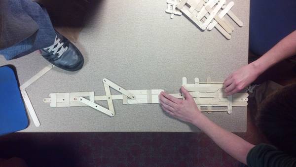
From these unassuming materials we were able to make gates for AND, OR, and NOT and came up with an easy method for connecting them, giving us the ability to make any other basic gate. An example of connected gates is below, in both states – an OR and a NOT connected to make a NOR gate.

Why did you do it?
You are suddenly transported to a new and unfamiliar environment (Think A Connecticut Yankee in King Arthur's Court) and you have to rebuild modern society out of primitive materials. Although you may not be able to fabricate transistors, you can still make computers out of bamboo and coconuts!
Just this idea that computation is free from the silicon and black boxes with which we so commonly associate it is one reason why this project is important. While the actual likelihood of finding yourself without modern technology is very low, it remains a fantastic educational tool for children who might not have access to normal electrical and computer prototyping materials. For children of non-technical parents who don’t have access to complex electrical or mechanical prototyping tools, a tutorial that can be done using common materials is very useful, and not daunting for parents to provide.
On a much more serious level, our popsicle design allows people with no previous notion of computing to be able to be introduced to basic logic through clear visual representation. Once the fundamental logic units exist, one can derive most other things, well, logically.
How did you do it?
We made our gates combining the above materials and puzzling over them for several days until we were able to come up with basic, robust, and repeatable logic gates.
Not Gate
A zero for a NOT gate is the input stick fully out. This causes the reciprocating linkage to push the output forward, creating a one.
Similarly, when the input is pushed forward in a one, the linkage transmits the forward motion into rotational motion and out again as backwards motion on the output, causing a zero for output.
Or Gate
A zero for either input to the OR gate does nothing so the output is pulled back to make a zero also.
Similarly, when either input is pushed forward in a one, the input stick pushes the bar forward, causing the output to also be pushed forward as a one also.
And Gate
If both inputs to the AND gate are one, the rubber band pulls the bar forward making output a one.
If either of the inputs is zero, the stop at the end of the input stick pulls back the bar connected to the output, dragging it against the rubber band to make a zero.
We used the Olin principle of spiral learning pretty heavily, because it became pretty clear early that we didn’t really know what we were doing – so we tried, failed, and tried again.
How can someone else build on it?
We made clear, step by step instructions on how to build the gates and some diagrams about how they can be attached. With enough time and popsicle sticks, you could theoretically make a computer out of these gates.
We would still recommend this as a good middle-school level demonstration of mechanical logic and computing, but we would recommend it as an exercise done by an entire class – teams of 2 or 3 build the gates, and then the gates are assembled at the end of the period into a complex logic circuit. This way, everyone feels ownership over the entire project, but you don’t run afoul of the attention span of middle schoolers. From a visual representation perspective, this is a fantastic demo. However, the quality of demonstration must be balanced with the time spent.
Areas for growth
- Figure out how to easily make an XOR gate without having to make it out of smaller gates. This isn’t necessary, but it would be helpful. With this XOR gate, it would be easier and more obtainable to make a full adder.
- Another gate that you don’t have to have in an electric context is a signal strengthener. The strength of the mechanical signal is reduced through NOT gates we found due to slippage in the joints (a 1 inch input would result in a .8 inch output or something similar).This gate would take for instance a .8 inch input and give a 1 inch output.
- Another gate that would be necessary in a larger construction would be a signal splitter. It would take in one input, 1 or 0 and output two 1s or two 0s. This would allow us to have more complicated circuits. Currently, if you only build in one dimension, you can only connect a gate to one other gate.
- Decrease throw of gates. This would enable us to make more efficient use of space. The downside of this is it increases the chances of errors or noise in the system occurring.
Workplan Reflection
Adherence to Schedule
We stuck to our workplan fairly well as far as time spent goes – we actually spent slightly more time than we planned to. It was a little more backloaded than we anticipated, but that happens with all projects, and this wasn't true to an appalling degree, only a small amount.
Re-scoping of project
We changed what we did slightly throughout the course of the project, as we realized that our initial goal would involve a lot of manual labor for much less educational reward. We came to the conclusion that, given our knowledge of computer architecture, we would make a larger impact by making gate design blueprints and recommending how they could be used as educational tools. The complex part for a middle schooler would not be the assembly of the gates, it would be the design and instructions to make them. Therefore, in the interest of maximum education for all, we rescoped our project…which leads nicely into our next point.
Why isn’t there a full adder like promised?
One of the major flaws in our schedule was our optimistic projection on the time it would take to make a gate. We estimated that it would take 15 minutes, putting a full adder (depending on implementation) at a little over 2 hours.
However, in actuality, each gate, if it was constructed carefully (so as to maximize efficiency of operation), took almost an hour. This meant that making a full adder would take 10 hours.
When you factor in the design time of the gates and the decisions of form factor, prototyping of possible designs and documentation, this was too lofty of a goal in the time remaining.