This is an old revision of the document!
Table of Contents
Optimizing a Pipelined CPU
Brendan Caporaletti, Chelsea Bailey, Jeffrey Hanford
The Vision
We made an optimized, 32-bit Pipelined CPU with features including: hazard avoidance, branch prediction, and MIPS compliance.
We began by creating a working 32-bit CPU with static branch prediction and data forwarding that was not quite compliant with MIPS architecture. The goal of this project was to use that CPU as a base for exploring optimization and timing. We then began the process of implementing new features over various iterations and comparing the pros and cons of each new version. The what, why, and how of each version are explained in much greater detail below.
This project appealed to all of us because it allowed us to build upon our knowledge gained in the final lab in Computer Architecture. That lab gave the assignment of creating a 32-bit MIPS compliant single-cycle CPU. We wanted to take that idea even further, challenging ourselves to create not only a pipelined CPU, but one with hazard avoidance. Beyond that we were fascinated by how CPUs have been optimized over time. We chose this final project, because of all the areas it allowed us to engage in: research of optimization, design of various systems, and finally synthesis with timing analysis.
V1 The Original CPU
IF
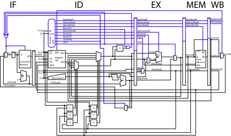
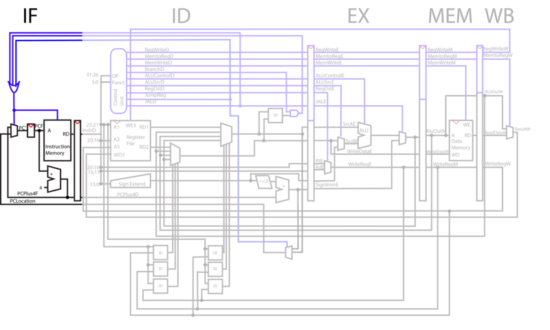
During the instruction fetch phase, the output of the Program Counter is fed into instruction memory. Instruction memory will pull the instructions from the register that corresponds to the input PC value and output them to the next stage of the CPU. The value of PC is then incremented by 4, as the addresses of instruction registers differ by 4. The mux selects to either take PC+4, or an input register to jump to based on the selector bit. This selection is based on whether or not at least one of three different jump control lines is high.
ID
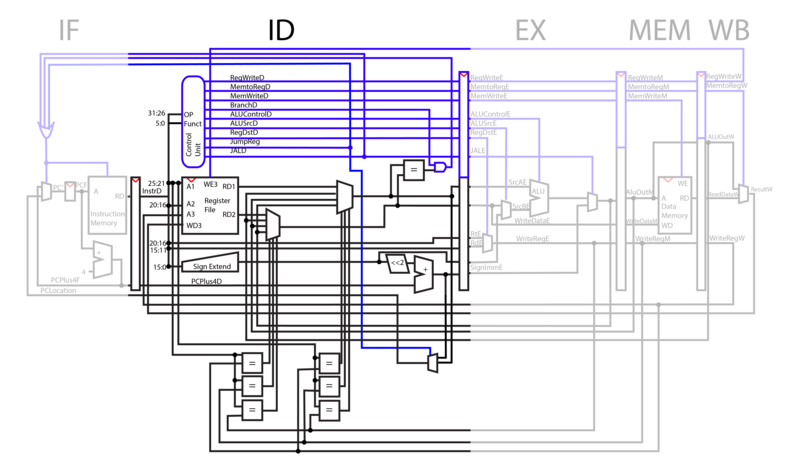
During the instruction decode phase, parts of the opcode are sent to the control unit, which decodes the two inputs, determines the function that those inputs correspond to, and outputs ones or zeros through each control line depending on the function.
Two addresses are pulled from the opcode and fed into the register file, which pulls the corresponding registers from the addresses.
As part of our pipeline optimization, the six comparators at the bottom of the diagram check to see if later registers being requested in later phases of the CPU are the same as the ones being operated on. If the registers are the same, the ID phase outputs the updated data instead of the original, outdated information in that register that has not yet been written back to.
In a jump operation, BRENDAN PUT STUFF HERE THAT IS GOOD AND ACCURATE ABOUT ALL THE JUMPSthe amount it should jump by is contained within 16 bits of the opcode. This register is fed through a sign extender, shifted by two, added to the current PC number and output to the next phase of the CPU.
If WriteEnable is high, the number being fed into WD3 is written to the write register A3 from the writeback phase.
[TALK ABOUT BRANCH COMPARATOR THING]
EX
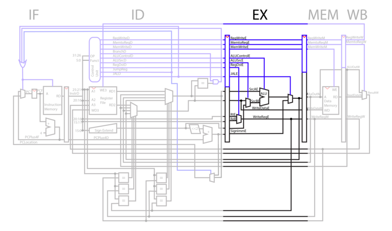
In the execution phase, ALU operations are performed on the registers pulled from the instruction decode phase. The ALU operation selected depends on the ALUControl line. For add immediate, instead of adding RD2 to RD1, the CPU selects the immediate line from ID and adds it to RD1 using the ALUSrc selector bit.
The register that is to be written to is decided by the RegDst line. In operations like Add, where two registers are added and a third is written to, Rd is used. In operations like add immediate, where only one of the input registers to register file is used, Rt is used.
MEM
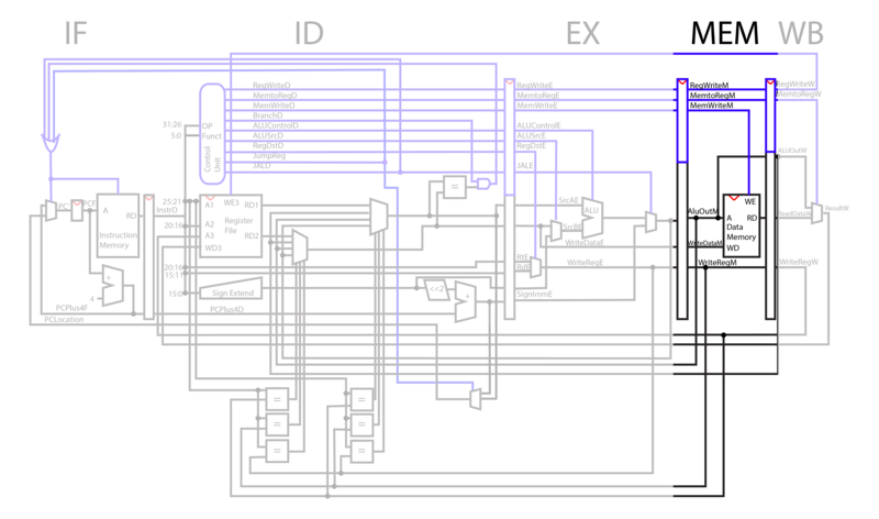
In the MEM phase, WriteData is written to the AluOut address if MemWrite is high. When MemWrite is low, data is read from WriteData register and output to RD.
WB
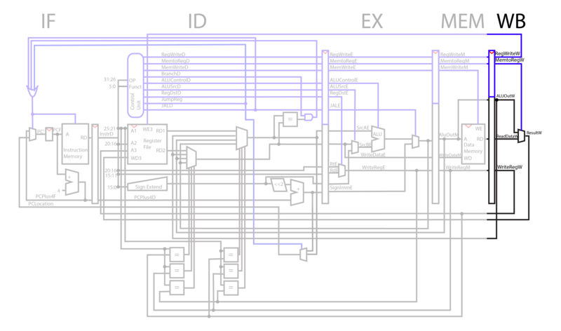
In the WriteBack phase of the CPU, the selector line MemtoReg selects whether to use the memory output or the ALU output. Result from WriteBack is fed into the register file in ID, and if WriteEnable is high, the data is written to WriteReg register from writeback.
Improvements
V2 MIPS Compliance
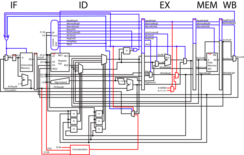
In our original CPU design, we treated branching in the same method as jumping, which was a different implementation from MIPS. To make our CPU fully MIPS compliant we had to add concatenation into the ID phase where we do our jumping. According to MIPS, branch commands are based on a delta where as jump commands require a target destination. The jump machine codes provides 26 bits which when concatenated with two 0's in the low order bits and the 4 highest order bits of the PC, provides the jump destination.
EXPLAIN JAL JR 11111 00000 THING
EXPLAIN JALE LINE MUX
V3 Jump Up
Once our design was MIPS compliant, it allowed us to implement another feature. The concatenation made jumping much quicker and therefore we decided to move it up into the IF phase. The sooner jumping can happen the less clock cycles we waste.
V4 Dynamic Branch Prediction
Our original solution for hazards related to branching/jumping was static branch prediction. We always assumed that we were not branching. When we began our final project, we knew that our branch prediction was area in which we greatly wanted to add improvements. After much research we settled on dynamic 2-bit prediction.
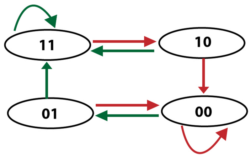
The idea behind dynamic prediction is that we are always changing our guess based on the accuracy of the previous guess. In the simplest case this is a one bit value. When a branch is taken the value is set to 1. When it is later not taken the value is set back to 0. A 2-bit predictor allows us slightly more accuracy. The diagram below explains how our 2-bit predictor works in the form of a finite state machine. The four states are strongly taken (11), weakly taken (01), weakly not taken (10), and strongly not taken (00). The green arrows represent when a branch was taken and the red arrows represent when a branch was not taken. Every time a branch is taken or not taken it follows the path dictated by those arrows and the state it is currently in.
Beyond the number of bits for prediction, there are still other details to be determined. For example, we could have implemented a global predictor. The global predictor merely stores one 2-bit value and uses this single value to determine action for all branches. We instead decided to create a cache and store a unique branch predictor value for each of the branches in the code. The figure below is a visualization of how this cache works. We index into the cache using low-order bits from the PC. In the rows of the cache we store not only the 2 bit predictor value, but also the branch destination. This way we do not have to recalculate the branch destination anytime after the first time the branch is taken.
Timing Analysis
Version 0 (No Ops)
| Phase | Clockspeed (ns) |
|---|---|
| IF | |
| ID | |
| EX | |
| MEM | |
| WB | |
Throughput:
Version 1 (Original)
Version 2 (MIPS Compliant)
Version 3 (Jump Forward)
Version 4 (Dynamic Branching)
Reflection
The whole process of this project was incredibly gratifying and overall successful, but we did face a lot of difficulties along the way. One of our biggest hurdles was synthesizing our design. None of us had previous experience with synthesis using XILINX and it had a good bit of a learning curve for us to surmount.

