This is an old revision of the document!
Table of Contents
Pipelined CPU, hazards eliminated
By Shivam Desai, Kris Groth, Sarah Strohkorb, Eric Westman
What did you do?
We used this project as an opportunity to model and simulate a pipelined CPU.
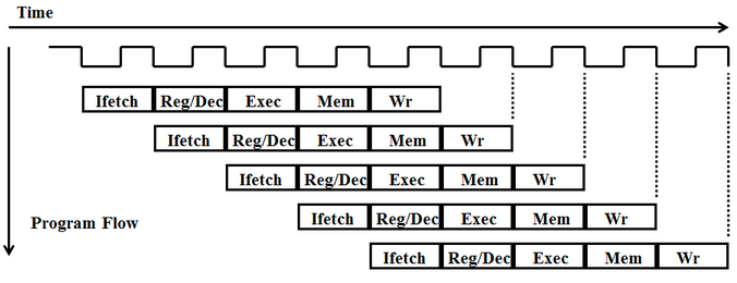
Pipelining a CPU increases efficiency significantly by dividing up the different functional chunks of the processor and assigning a different task to each one. There are five such functional stages in our processor: Instruction Fetch (IF), Instruction Decode (ID), Execute (EX), Memory (MEM), and Writeback (WB). A program is compiled to a set of “instructions,” which are tasks that the CPU can perform in a single pass through the five functional stages. The pipelined CPU feeds instructions one at a time through the “pipe.” Once an instruction has finished in one stage (which takes one clock cycle), it moves to the next stage (for example from IF to ID) and the next instruction in the program will be put in the pipe immediately behind it. This scheme allows the processor to be executing up to five different instructions at once. Splitting the pipe up into many small stages allows for a faster clock cycle and more parallel computing, speeding up the processor and increasing its throughput.
We spent a large portion of the project designing our CPU to handle various data, structural, and control hazards. Even very simple programs written in Assembly code often introduce hazards which, if left unaddressed, will cause the program to fail at execution. These hazards are functions of the pipelined architecture and don’t arise in a single-cycle or multi-cycle CPU.
Why did you do it?
Most modern processors use some form of pipelining in their functionality, so it seemed like a natural step for us to implement one in Verilog to get a good working knowledge of the cogs and wheels behind the magic. In Lab ‘b011 we implemented a multi-cycle CPU which inspired us to take it a step further and implement a pipelined CPU that handles hazards. This implementation for the final project is worthwhile as it enables us to execute many programs written in Assembly.
How did you do it?
Pipelining
The basic structure of our pipelined CPU builds off of the structure we implemented for the multi-cycle CPU in MPb011. The basic structure of the multi-cycle CPU in behavioral Verilog is:
always @(posedge clk) begin

    case (state)
        IF: begin
        ...
        end

        ID: begin
        ...
        end

        EX: begin
        ...
        end

        MEM: begin
        ...
        end

        WB: begin
        ...
        end
On each clock cycle, the CPU operates the architecture specified in the appropriate case, depending on which stage the current instruction is in. In order to expand this to a pipelined CPU, we created five different case structures, one for each different possible instruction slot (since our pipeline has five different stages, five different instructions may be executing at any given moment).
always @(posedge clk) begin

    case (stateA)
	...
    case (stateB)
	...
    case (stateC)
	...
    case (stateD)
        ...
    case (stateE)
	...
In order to fill up the pipeline, instruction slot A starts in the IF stage, and all other slots start in the idle state. Each instruction while in the IF stage sets the next instruction slot to the IF stage, so that the CPU starts executing the next instruction.
One major change between the multi-cycle and pipelined CPU is the introduction of registers between the major hardware components in each stage. Because each stage executes within a clock cycle, registers are placed between each stage in order to hold and propagate data through the pipeline that is needed throughout different stages of execution.