FPGA Piano
Abstract
Never understood why a piano has so many keys? Think a single octave is more than enough? The FPGA piano allows you to practice your favorite scales or chords and even lets you listen to some of your favorite tunes while you take a break. Our piano has two different modes: Piano Mode and Song Mode. In Piano Mode, the user can toggle the switches to play different tones and chords from the eight notes in an octave. In Song Mode, the user can depress the buttons on the FPGA to play four different recorded sequences: scales, a simple repeating pattern, Happy Birthday, and (FPGA)Piano Man.
Reasoning
We undertook this project because it offers a synthesis of digital logic synthesized on an FPGA and the world of analog signals that show up in other classes. Additionally, the piano provides a fun opportunity to explore musical interactions with the FPGA and translate between the frequencies of electronics and the frequencies of hearing. Lastly, we spent a lot of time this semester modulating clock frequencies and coordinating timing, so we wanted a final project that allowed us to demonstrate our understanding of these concepts.
Implementation
Note Tones
The basis of the piano’s functionality is its ability to produce a variety of square waves of different frequencies that match the tones humans associate with the keys of a piano. We accomplished this in verilog by creating a module which takes a clock divider value as a parameter. The module counts the positive edges of the 25 MHz FPGA clock signal and inverts the value of an output wire whenever the count reaches the clock divider parameter. We created instances of this module to output each of the 8 base tones we desired: C4 (262 Hz), D (294 Hz), E (330 Hz), etc., all the way to C5 (523 Hz). We later added a few extra tones that we needed for Song Mode. If the FPGA clock is altered to 50 or 100 MHz using the external jumper, the counter will increment twice or four times faster, increasing the output by one or two octaves.
Piano Mode
When no buttons on the FPGA are pressed, the piano is in Piano Mode. In this setting, each note in the C major scale is controlled by one of each of the eight switches on the board and outputs to an individual GPIO pin. Eventually, we connected these eight output pins to the inputs of our adder circuit so that a single speaker will play the combined chord of the notes are active (ie. the switches that are high.) We extended this mode to play three consecutive octaves by switching the clock between 25 MHz, 50 MHz, 100 MHz using on clock adjustment jumper on the FPGA.
Song Mode
Song Mode is activated when the user presses any of the four buttons on the FPGA. Each button corresponds to one song. When a song is chosen, a counter begins to increment every 1/16th of a second. This is done using a 16 Hz signal created with the rest of our note signals. On each positive edge of the system clock, if the 16 Hz signal is high a flag is checked to see if the counter has already been incremented during this high period. When the 16 Hz signal switches to low, the flag is reset. We use the counter as the index into an array in which the song notes are stored. The note value at the corresponding index is used in a case statement to determine which pins should output which notes. Currently the case statement only outputs a single note through pin one as none of our initial songs required chords. However, upon further development additional note encodings could be created to output up to 8 notes simultaneously using the 8 GPIO pins. This offers a very flexible and extendable framework for playing songs. For example, if shorter notes or rests in a song were desired, the 16 Hz song counter signal could be sped up to a 32 Hz signal.
Song Data Generation
The FPGA stores song sequences as arrays of 4-bit, 1/16th second tone chunks. By hand this data input would be tedious and error prone. To begin the process of easing and automating song recording we wrote a short Python script that allows the user to input a sequence of note, repetition-number pairs and have the verilog code to input the song data returned. A user input of “4,4” would add four lines of “song[<index>] = 4’d4;” to a list of commands where <index> automatically fills in the incrementing index of the note and the note “4” corresponds to an F. The result of “4,4” is adding an F quarter note to the song. Additionally, the note “0” can be used to specify a rest. Even at this early stage the script sped up song creation significantly and reduced errors. However, a further extension of this script could allow simpler input, the ability to save partial songs, mapping from a note string to the note number used by verilog, or many other ways to allow faster creation of more complex songs.
Analog Circuit
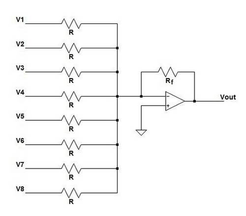
For certain songs and Piano Mode we wanted the ability to play multiple notes at once as chords. This meant that we would need to be able to add any combination of our eight FPGA output signals (notes) together. We chose to build an analog summing amplifier because the circuit was reasonably easy for us to understand and implement quickly. The eight outputs of the FPGA are the eight voltage inputs to our voltage adder. The output is a scaled version of the sum of the input voltages and it is used as the input to the speaker. A diagram of the circuit is shown below. We used this site for reference and to choose our resistor values: http://www.electronics-tutorials.ws/opamp/opamp_4.html.
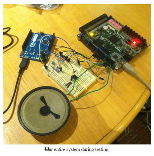
We use a TLO81CP operational amplifier with Vcc = 5V and -Vcc = GND. We used an 8 ohm speaker. R = 1k ohm and Rf = 10 ohm. V1, V2, … V8 are the signals coming out of the FPGA. Vout is the signals added together and is the input to our speaker. To test our system, we used an Arduino Leonardo to provide a 5V power supply.
Testing
To test our initial octave, we wrote a simple test bench that creates each note module and allows us to visually inspect the waveforms in ModelSim to ensure that the notes in our octave matched the frequencies for a C scale. This enabled us to verify relative period size and timing, but not much else as audio signals are significantly slower than the system clock and are very close together. As a supplemental form of testing we loaded our octave onto an FPGA and checked that the notes sounded correct by playing the scale a few times. This proved to be a very useful form of testing because our ears are quite good at detecting an incorrect octave or chord.
To test our songs, we loaded the song data onto the FPGA and played it a couple of times, ensuring that notes and timings were correct. We also had a number of our friends listen to it and try to guess the song to gauge the quality of our versions. Knowing that we could not perfectly reproduce songs using our system we judged a song to be sufficiently correct when it could reasonably recognized as the original song.
Difficulties
Since no one in our team is particularly knowledgeable about music, we had to spend a bit of extra time figuring out how to encode proper octaves, notes, and frequencies for our piano. We also had to spend time figuring out how to make notes play for different amounts of time during songs so that we could play a range of eighth, quarter, and half notes. One difficulty that we did not find a particularly elegant solution to is the storage of song data. Our current solution involves hard coding a note to be played every 1/16th of a second which requires lots of space in the code and time for the implementer.
Continuing this Project
If another team were interested in continuing this project in the future, the next steps would be to expand our song and note repertoire. To do this they could to find a method to execute slurs between notes and create notes for every key on the piano and expand the note encoding to support each note and common chords. Our code is available at https://github.com/benkahle/fpga_piano and is comprised of piano.v which includes the piano logic, pianoTopLevel.v and piano.ucf which allow Xilinx synthesis, piano.do which runs a ModelSim simulation and shows waveforms of important signals, and songGen.py, the Python script for song data generation.
Reflection
System Stats
As a comparison to some of the other systems we have synthesized onto an FPGA this semester, the FPGA piano required the following structure components:
- 1 112×4-bit ROM (Happy Birthday song data)
- 1 183×4-bit ROM (Piano Man song data)
- 1 43×4-bit ROM (“Random” song data)
- 1 8×4-bit ROM (Octave song data)
- 1 4-bit Adder
- 3 8-bit Adder
- 15 24-bit Up Counters
- 56 Flip-flops
Work Plan Reflection
Because of volatile finals schedules we were unable to follow our original work plan but still managed to meet often and accomplish each task within a reasonable time frame. It was fortunate that we had scoped our green feature set to be relatively easy to quickly implement. This allowed us to be flexible about which of our yellow features we implemented.We chose to pursue switching octaves and playing chords because we were excited about the prospect of being able to play a wider variety of songs. This flexible work plan structure with green, yellow, and red features allowed us to get something simple working quickly and then have fun extending the project.

