This is an old revision of the document!
Table of Contents
Piano and Chip Tunes with an LFSR on an FPGA
by Casey Alvarado, Mika Ichiki-Welches, Cynthia Chen, Nitya Dhanushkodi and Zoher Ghadyalli
What did we do?
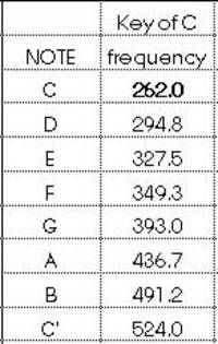
We made cool sounds with a Field Programmable Gate Array (FPGA)!!! We made a piano with the octave frequencies starting at middle C going to the octave above middle C with the following frequencies.

Piano on an FPGA
We built a piano on an FPGA by outputting frequencies corresponding to the musical notes of a piano. For example, the note A is at 440 Hz. We created an up counter that divided the frequency of a 25 MHz clock by how many times a wave has to wait to oscillate at the desired musical note frequency. We divided the clock by how many times it takes to get the correct frequency of 440 Hz, and assigned each note's frequency to the GPIO pins (input/output pins of the FPGA). We then just jumped these pins to a breadboard and connected this frequency output to a speaker.
We enabled each note frequency using the switches on the FPGA as enables in the top level module that the FPGA synthesizes. You can enable as many switches at once and play notes or chords.
FPGA Piano Problems
In order to divide the clock by how many times it takes to achieve our desired frequency we establish a counter that increments on each positive edge of the clock. Initially, following example code we found online, we set up a 16-bit counter.
In terms of dividing the frequency, the lower the frequency desired, the higher the count had to be. We were looking at the most significant bit of our count, which oscillated at the desired frequency. However, for lower frequencies, the count had to be higher and higher. In doing so, we actually had to use 17 bits, instead of 16 for our count. In the same way, moving to higher frequencies decreased the count and then we needed to change which bit we were assigning as our frequency output, because the lower counts may not have exceeded the value of the 15th bit.
In addition, we realized that one of the GPIO pins on the FPGA was not outputting the expected amount of volts. All of our frequencies coming out of the FPGA oscillated from 0V to approximately 3.3V. However, out of one GPIO pin, we were only measuring a maximum voltage of 400 mV, which was not enough to drive the speaker. We know that this is a problem with the FPGA and not our code because when we connect the A note to a different pin, it works. It appears that something is happening with that pin and it is not providing the correct amount of correct.
Chip Tunes using an LFSR on an FPGA
After successfully completing the piano portion of this lab, we decided to experiment a bit with an LFSR, which is a linear-feedback shift register whose input bit is a linear function of its previous state.
The most commonly used linear function of single bits is exclusive-or (XOR). An LFSR feeds two of the bits currently in the shift register through the XOR gate. The result is the bit that is shifted into the register. In this way, the input to the shift register is dependent on the current state of the shift register.
The initial value of the LFSR is called the seed, and because the operation of the register is deterministic, the stream of values produced by the register is completely determined by its current (or previous) state. Likewise, because the register has a finite number of possible states, it must eventually enter a repeating cycle. However, an LFSR with a well-chosen feedback function can produce a sequence of bits which appears random. For our purposes, this would produce multiple frequencies.
Really old video-games used LFSRs
Playing a Programmed Song with the Press of a Button
hot damn
Why did we do it?
Because lolz
this part should be a paragraph long
How did we do it?
This portion can assume an audience that has taken Computer Architecture, but don’t get burdened by buzzwords. A sure sign of a bad engineer is over reliance on acroynms.
The first thing we needed to do was slow down the clock. We ran the clock through an Up Counter so that the flip flops would wait for so we used an upcounter to divide the clock appropriately to the correct signal at 440 Hz.
Run the piano/song/LFSR
You can synthesize either the piano/song mode on the FPGA or the LFSR chip tunes on the FPGA.
