This is an old revision of the document!
Table of Contents
Topic Statement
This project had the wonderfully original goal of creating a sort of calculator capable of performing addition, subtraction, and multiplication with a workable subset of the rationale numbers (termed “floating point numbers”) while attempting to make optimizations to make the computation reasonably fast. Our unit is designed so that it can be attached to other modules and used within other designs and was inspired by the the age of floating point coprocessors that could be bought separately and attached to home computers.
Significance
Although floating point calculation was touched upon in our class when we discussed representing numbers, all labs and homeworks involved strictly integer calculation. Knowing that floating point representations introduced multiple complications not present in integer or fixed point arithmetic, we wanted to investigate the process for representing and doing computation with floating point numbers. While the procedures for addition, subtraction, and multiplication are well known to humans, we often take for granted what steps these operations involve. For instance, when adding or subtracting with decimals, we automatically known how to align our digits so that the decimal point is correctly placed. When multiplying 5 * 3, we don't add 5 three times; instead, we likely have our multiplication tables up to 10*10 (probably even higher) memorized. Ideally, those reading this document will appreciate the complexity of the most basic arithmetic, long forgotten in the era of elementary school. Surprisingly, our implementation of addition, subtraction, and multiplication in the computer is quite human!
Method
Representation
The first and probably most important design decision we made was on our representation. There are many ways to represent rationale numbers and each has its own tradeoffs to be made.
- “IQ” notation. This representation tells us exactly how many bits are before and after the radix. This is obviously not what we wanted because it is by definition fixed point!
- IEEE 754 is a standard that all modern computers understand that uses a sign bit, exponent, and fraction to represent a number.It is designed to have no redundancy and be very space efficient. Unfortunately, it is quite awkward to do arithmetic with.

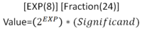
- Scientific notation includes an exponent and a fraction. It's pretty convenient to do computations with. Addition requires normalizing exponents and then adding the fraction while multiplication requires multiplying the fractions and adding the exponents. It's perfect! But…it's in base ten.
- Scientific notation in base two is a reasonably simple representation we eventually ended up using. All exponents and fraction sections are signed. This representation is quite inefficient as there are many ways to represent the same value, but it is convenient to work with, especially on our time scale.


Hierarchical Block Diagram
All modules are designed, simulated, and tested in Modelsim PE and are written in Verilog.
Complete FPU
Addition/Subtraction
Addition would be as simple as it sounds if there was no exponent to deal with. Before operands enter our adder, they must first be normalized to the larger of the two exponents. We do this by finding the difference of exponents, and shifting the smaller operand by the difference. This process is vulnerable to losing precision, especially if one exponent is much larger than the other. The larger exponent is passed out to the result, and the shifted operands are then added as usual. Subtraction is identical as negatives are dealt with nicely in two's complement notation. Normalizing to the exponent in subtraction is the same as in addition.
Multiplication
Multiplication starts with making sure both operands are positive. If they're negative, they aren't anymore! The two's complement representation of a negative number was troublesome to deal with, so we removed it and dealt with it at the end by looking at the signs of the inputs. That said, multiplication with a computer is surprisingly human, behaving similarly to long multiplication from 3rd grade. To try this method yourself, write down operand A and operand B. If the rightmost place of B is 1, add the value of A to an accumulator. Then, shift A to the left 1 place, filling in the empty place with a zero, and shift B right one place, again filling in the empty with a zero. Repeat the cycle of adding A is the rightmost place of B is 1 until all places of B are zero. After this shift and accumulate process is done, we change the sign of the output to match the inputs. The multiplier will display its result as soon as it is ready (it sees that B is all 0). To find the correct exponent in a multiplication operation, just add the input exponents. If the exponents cause an exception by having a carryout or overflow, an output flag will indicate that the exponent displayed is not valid.
Carry Select Adder
The carry select adder is a special type of adder that resolves more quickly than a ripple adder. It saves time at the cost of additional hardware by calculating the result of smaller groups of a larger bit both with and without a carry in. When the carry in of the previous group is known, a mux selects whether the value with or without carry in makes it to the output. While a ripple adder takes (adders)*(time per adder) to complete, the carry select adder takes (adders in group)*(time per adder)+(number of muxes)*(time per mux). By choosing the correct group size, the carry select adder can beat a ripple adder by performing all adds in parallel and only selecting muxes (which are pretty damn fast) serially. By counting how many NAND gates the longest signal needs to flow through in both our mux and adder, we determined that we could make the fastest 64-bit adder with 8 groups of 8 adders.
Multiply by -1
As it turns out, multiplication is a lot easier with unsigned numbers than signed numbers. To get around this, we included a unit that will multiply by -1 (it just reverses the 2's complement) if an input to our multiplier comes in negative. The output is then adjusted accordingly if it must be negative.
Other (Modules that are either trivial or have no gate level diagram)
- Barrel Shifter - Shifts an input in either direction by a specified amount. Unique because it can shift several places simultaneously.
- 1-bit Full Adder - Adds two single bits and has a carry in and carry out. It is building block for our entire design.
- Mux - Selects an input and maps to an output.
- Set on Less Than - Will emit true if operand a is less than operand b.
- Sign Extension - Used to make smaller numbers go into bigger ports. Just sticks a bunch of 0's on the left of a positive number, or 1's on a negative number.
- Register - Holds data until new data comes in on the next clock cycle.
- Up Counter - Increments a value by 1 every clock cycle until a certain value is reached. Our up counter must be reset at the start of every multiply operation.