Table of Contents
Binary Clock
by Emily Wang ('16) and Sophia Seitz ('16)
Computer Architecture, Fall 2013
What did we do?
For our Computer Architecture final project, we made a clock that tells the time in binary using Verilog, a Spartan 3 FPGA, and some LEDS. Quite spiffy indeed.
Given a 50 Mhz square wave, we can add some structures made out of logic gates to create a clock that can tell real-life time and behave according to the 24-hour pattern our lives revolve around. Simply put, we needed to write Verilog code that would 1) divide the 50 MHz square wave into a 2 Hz signal, 2) update the time values every second, and 3) allow capabilities to set the clock to the current time in real life. Afterwards, we tinkered with the hardware: uploading the code onto a FPGA (field programmable gate array), connecting the FPGA to 17 LEDs, and even creating a nice casing for the device. Read on for more details!
Why did we do it?
We knew that we wanted more experience with the FPGA beyond the MP3 lab option. Most of our exposure with programming in Computer Architecture has been with Verilog simulations in ModelSim or MARS Assembly, which is obviously different from uploading to and debugging code running on the FPGA (for example, frequency dividers in structural with flip flops work fine in ModelSim, but caused unexpected troubles on the FPGA). Therefore, we chose to run our Verilog code on an FPGA to help create the binary clock in real life.
Also, we wanted to pursue a project that could be used to help teach others about Computer Architecture topics, such as binary numbers, multiplexers, adders, and frequency dividers, which are all essential pieces of our binary clock.
How did we do it?
This project has several “subsystems” for incrementing the clock as time goes by, obtaining the correct frequency, and being able to set/reset different parts of the binary clock. Each subsection below describes a mechanism used in the binary clock.
Seconds, Minutes and Hours
Below is the system we use for keeping track of the values for seconds, minutes, and hours. In this diagram, green means that this is a “black” box. Blue signifies that something is a register, where we are storing information, black indicates a wire, pink indicates a gate, and orange represents inputs and outputs.
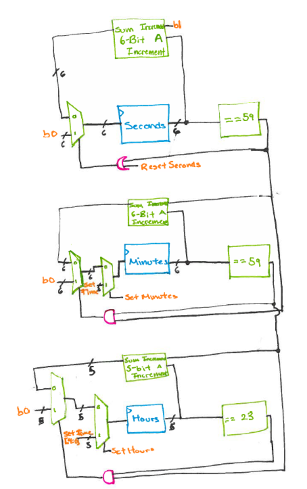
In the diagram above, we increment the value for seconds on each positive edge of our signal (a 2 Hz signal). Then, we check if our previous seconds value was equal to 59. If our previous seconds value was equal to 59, then we need to reset seconds, and increment the minutes. We also reset seconds if ResetSeconds is high.
For the minutes, we only increment if the seconds was previously equal to 59. Like the seconds system, we also have to check if minutes is equal to 59. If this is the case, and seconds equals 59, then we know that an hour has passed and that we need to increment the hours value. In addition to just generally incrementing minutes, we also can set the minutes in our clock. If SetMinutes is high, then minutes is instead set to the value inputted in SetTime.
The hours behaves exactly like the minutes but with one slight change. Because hours only go up to 23 on a clock, we only need 5 bits, and not 6, like we have for seconds and minutes, to keep track of the time. This also means that we are checking to see if hours equals 23 and not 59 to see if we have to reset hours. Like minutes, we can also set hours. When SetHours is high, hours is set to the 5 least significant bits of SetTime.
Incrementing
Below is our diagram for our incrementing block. The diagram pictured below is for a 5-bit increment, and for the 6 increment, we just add more 1-bit adders until we have enough bits.
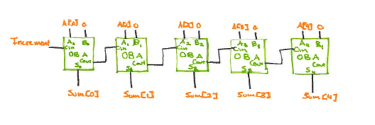
In this diagram, we chain the 1-bit adders together by their carry bits. Our inputs here are A and increment, and our outputs are Sum. The reason that we do not have B as an input or carry out as an output are that we do not need them. We are adding 1 each time using the carry in input, and we know that we will never have a carry out because 59 and 23 are not the largest numbers that can be represented in 6 and 5 bits, respectively; we know that we will reset before we need to carry out.
OBA
Below is the gate diagram for a 1-bit Adder.
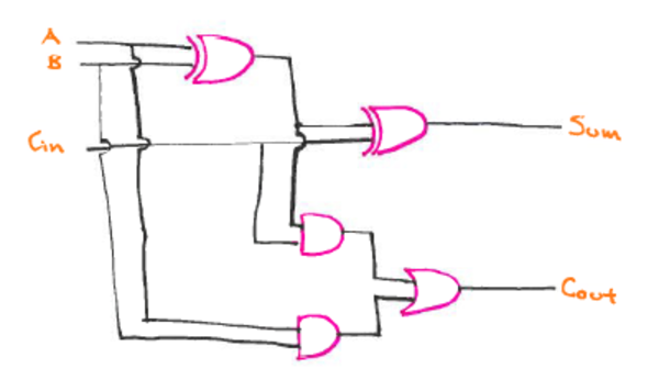 Just in case we've forgotten how a 1-bit adder works, Sum is 1 when there are an odd number of high inputs. CarryOut is high when there are more than 1 high inputs.
Checking Equality
Below is the gate diagram for checking whether the input is equal to 23.
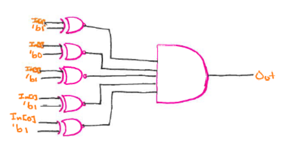
To check equality, we use a bit-wise XNOR gate, and then input each resulting bit into a 5-input AND gate. The output of this gate is high when the input equals 23, and low any other time. In other parts of the clock, we have to check equality with other numbers. To do this, we just change the constants inputted into each XNOR gate and the number of bits we have.
Mux
We use muxes to determine what to set the hours, minutes, and seconds registers to. This is a 1 bit, two input mux.
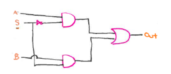 When we need more bits, we just stack muxes on top of each other, inputting one bit of the value into each mux, and setting the select bits to be the same.
Register
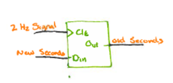
Our registers are pretty simple; they consist of D flip-flops, and are written to each second (on the positive edge of the 2 Hz signal.)
Above is a 1-bit register. For hours, we have 5 registers, and for minutes and seconds we have 6 registers each.
Frequency Dividers
The other part of this clock is getting a signal that has the right frequency to update the seconds, minutes, and hours with the correct timing. The FPGA has a 150 MHz clock, which we divide down to a 2 Hz signal. To do this, we use a combination of 2x and 5x frequency dividers. Our frequency divider chain is pictured below.
 The output of each frequency divider, which can be though of as the new clock signal, is fed into the following frequency divider. Eventually, we've divided our 50 MHz clock signal down to one that switches every 2 Hz. To do this, we use 8 5x dividers and 5 2x dividers.
5x Divider
Below is our diagram for the 5x frequency divider.
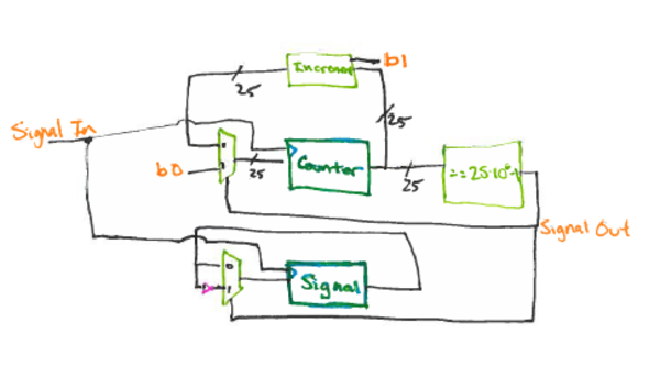 In order to achieve a 5x frequency divider, we use two registers. We have one (3 bits) to act as a counter, and another (1 bit) that stores the output signal. On each positive edge of the clock, or input signal, we increment the counter. When the counter reaches 4, we reset the counter and invert the output signal.
2x Divider
The 2x frequency divider is much simpler.
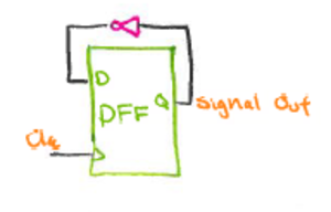 It consists of just one D flip-flop. The value stored inside the flip-flop is inverted every positive edge of the clock, so the frequency is divided in half.
Video
A video of our working clock can be found here: https://www.youtube.com/watch?v=ixKasWFv3TY
How can someone else build on it?
Code
The current code for this project can be found at https://github.com/greenteawarrior/BinaryClock
Feel free to fork this repository and play with the binary clock! Also, let us know if you do anything interesting. :)
Schematics
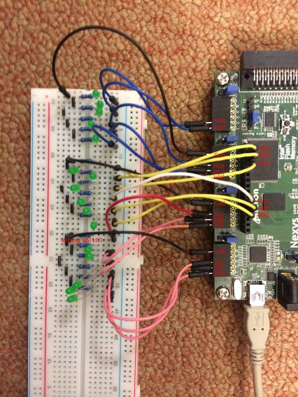
There is not a ton of electrical circuitry in this project, the exception being wiring LEDs into the FPGA. A picture for that is below.
Each of the LEDs' anodes is wired to a pin in the headers on the FPGA. The cathode is wired to a resistor and then ground. For our final iteration, we used common anode RGB LEDs, which have three cathode pins, one for R, G, and B. To change the color, we simply wired different resistors to each pin.
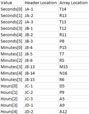
In addition, since the wires in the picture are a bit messy, here is a table of value, pin, and array location.
Build instructions
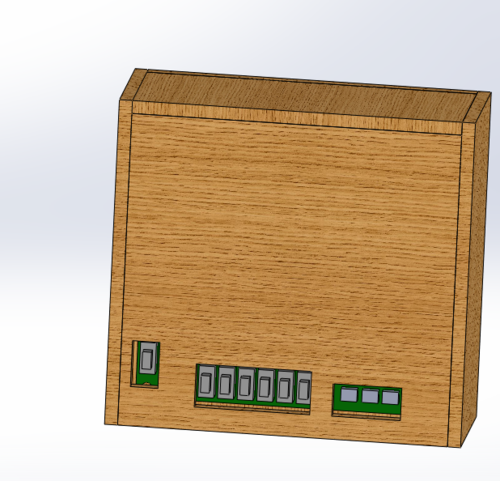
For our project, we built an case for our clock. We did this by laser cutting 3/16 inch MDF, and then gluing the case together. The CAD for the casing and a rudimentary CAD of our FPGA, the Spartan 3, can be found here:
*The github repository (includes code and CAD) can also be very easily downloaded as a .zip file if that is preferred. Please email Emily Wang or Sophia Seitz if you have any technical difficulties with obtaining the open source files. Thanks!*
We have a folder of the CAD files involved in creating the binary clock on the github repository : https://github.com/greenteawarrior/BinaryClock/tree/master/CAD
(Tolerances calibrated for cutting with a Trotec Speedy300 laser cutter - as always, prototype the LED diameter tolerances to prevent excessive filing/post-processing!).
Some screenshots of the assembly in SolidWorks:
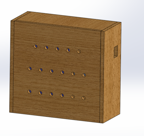
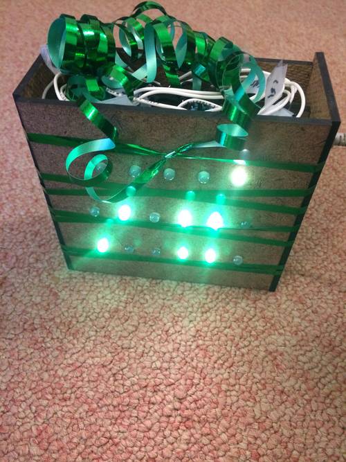
Here is a picture of the finished product!
Gotchas
- For some reason, the FPGA does not play well with frequency dividers implemented in structural verilog (i.e. lots of flip flops) when you're trying to display something tied directly to the clock signal. We still aren't sure exactly why this happens, but writing one big frequency divider in behavioral verilog seems to work well enough. This may involve exploring with the Digital Clock Manager feature in the Xilinx software, but it did not seem appropriate for the ultimate 2Hz frequency we desired. There's one warning message, which can, as far as we can tell, be ignored. The clock still works, and seems pretty accurate.
- When writing the .ucf file, be sure to check where your outputs and inputs map. The switches and pins 7 -14 on header J8 map to the same place, so you can use only one or the other.
- If you're set on the color of the LEDs, and want to have a specific one, make sure they work. We tried to make our clock have orange LEDs, using some RGB LEDs. They appeared to work when we turned the FPGA on, but when we started running our code, they turned greenish. We think this is because the FPGA outputs a different voltage when it is on, as opposed to when it is running a program.
Work Plan Reflection
We actually did pretty well sticking to our work plan. We finished writing code ahead of schedule, and then moved on to making the casing. The one big unexpected timesink was getting the LEDs working. We spent quite a few hours getting the color we wanted and soldiering, just to have them be a different color in the end.
Possible Future Steps
- Make the LEDs actually orange (This was Sophia's intended color for the display LEDs.)
- Add color changing LED pattern logic! (Rainbows, anyone?)
- The clock is fairly accurate, but does get off by a few seconds every couple hours. The frequency dividers could use some fine-tuning.
- Add some code to prevent the user from setting minutes or seconds to values above 60. (same concept for setting hours above 24)
- Make a PCB instead of the breadboard wiring we currently have.
- In addition to the time values, we could also have the clock display date (day of the week, year, etc).

