Table of Contents
Pipelined CPU, hazards eliminated
By Shivam Desai, Kris Groth, Sarah Strohkorb, Eric Westman
What did you do?
We used this project as an opportunity to model and simulate a pipelined CPU.
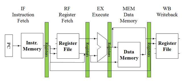
Pipelining a CPU increases efficiency significantly by dividing up the different functional chunks of the processor and assigning a different task to each one. There are five such functional stages in our processor: Instruction Fetch (IF), Instruction Decode (ID), Execute (EX), Memory (MEM), and Writeback (WB). A program is compiled to a set of “instructions,” which are tasks that the CPU can perform in a single pass through the five functional stages. The pipelined CPU feeds instructions one at a time through the “pipe.” Once an instruction has finished in one stage (which takes one clock cycle), it moves to the next stage (for example from IF to ID) and the next instruction in the program will be put in the pipe immediately behind it. This scheme allows the processor to be executing up to five different instructions at once. Splitting the pipe up into many small stages allows for a faster clock cycle and more parallel computing, speeding up the processor and increasing its throughput.
We spent a large portion of the project designing our CPU to handle various data, structural, and control hazards. Even very simple programs written in Assembly code often introduce hazards which, if left unaddressed, will cause the program to fail at execution. These hazards are functions of the pipelined architecture and don’t arise in a single-cycle or multi-cycle CPU.
Why did you do it?
Most modern processors use some form of pipelining in their functionality, so it seemed like a natural step for us to implement one in Verilog to get a good working knowledge of the cogs and wheels behind the magic. In Lab ‘b011 we implemented a multi-cycle CPU which inspired us to take it a step further and implement a pipelined CPU that handles hazards. This implementation for the final project is worthwhile as it enables us to execute many programs written in Assembly.
How did you do it?
Pipelining
The basic structure of our pipelined CPU builds off of the structure we implemented for the multi-cycle CPU in MPb011. The basic structure of the multi-cycle CPU in behavioral Verilog is:
always @(posedge clk) begin

    case (state)
        IF: begin
        ...
        end

        ID: begin
        ...
        end

        EX: begin
        ...
        end

        MEM: begin
        ...
        end

        WB: begin
        ...
        end
On each clock cycle, the CPU operates the architecture specified in the appropriate case, depending on which stage the current instruction is in. In order to expand this to a pipelined CPU, we created five different case structures, one for each different possible instruction slot (since our pipeline has five different stages, five different instructions may be executing at any given moment).
always @(posedge clk) begin

    case (stateA)
	...
    case (stateB)
	...
    case (stateC)
	...
    case (stateD)
        ...
    case (stateE)
	...
In order to fill up the pipeline, instruction slot A starts in the IF stage, and all other slots start in the idle state. Each instruction while in the IF stage sets the next instruction slot to the IF stage, so that the CPU starts executing the next instruction.
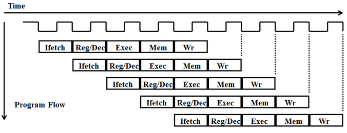
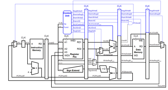
One major change between the multi-cycle and pipelined CPU is the introduction of registers between the major hardware components in each stage. Because each stage executes within a clock cycle, registers are placed between each stage in order to hold and propagate data through the pipeline that is needed throughout different stages of execution, as shown below.

Hazard Handling
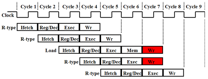
The first hazard we addressed was the one known as a “structural hazard.” There are five functional phases of the CPU, but only the Load Word instruction uses all five. It is very likely that a program will require different instructions to access memory or the register file at the same time. This can cause two instructions in different phases of the CPU to try and write data to the same place at the same time. The following figure shows the hazard for an R-type instruction and Load Word:
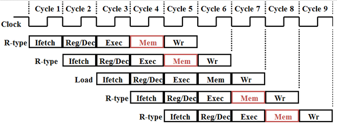
We avoided this hazard by forcing each instruction to go through all five phases of the CPU, regardless of whether or not the instruction needs all five. This assures that there will never be two instruction in the same phase at the same time. The following figure shows dummy MEM phases added to the R-type instructions to avoid structural overlap:
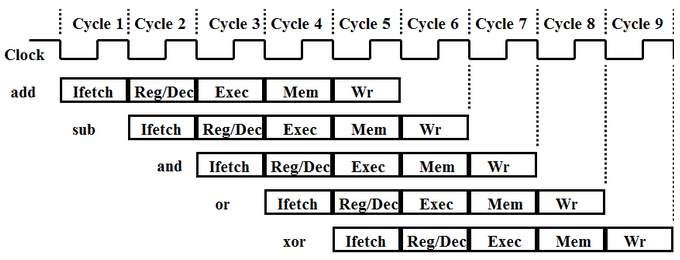
Some programs may have instructions that need data that is modified by one of the previous few instructions. This could be data in the register file, memory, or a cache (if caching were implemented). Regardless of where this data is to be stored, however, if a following instruction needs it before it has been written to its destination, that instruction will give the wrong result. This can be avoided by “forwarding” the needed data to the EX phase of the instruction that needs it. The following diagram shows an example of this data hazard where the SUB, AND, and OR instruction all require the result of the first instruction before it has been written:
With a forwarding system implemented, the program diagram should like the following:
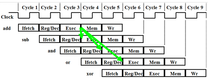
where the green arrows indicate forwarding of the result from the EX phase in the ADD instruction to the following three instructions. The ID phase of the final instruction (XOR) begins when the ADD has written the result, thus the data does not need to be forwarded because it can be read.
Another hazard arises from the way that the CPU keeps track of its progress when running a program. In the IF phase of each instruction that the CPU can handle, the CPU updates the “program counter,” which monitors the location that the CPU has reached in the program, but some instructions (mainly the ones used to perform loops or if statements) reset the program counter in later phases. Resetting the program counter in a later phase is a problem because the CPU has already started executing the next sequential instructions!
To sidestep this issue, we implement a “guess and check” system. Whenever there is an instruction that will or may reset the program counter, we assume that it will not and continue executing normally. If and when it does reset the program counter, we signal for the following instructions which have already entered the pipeline to stop executing by the MEM and WB stages (before they actually make any changes). After the PC is reset, the pipeline loads the next correct instruction and continues the program accordingly.
How can someone else build on it?
Work Plan Reflection:
Our goal for the project was to build a pipelined CPU that handled at least one hazard and process more instructions than we have been doing for the labs. We were not able to get the pipelined CPU to be fully operational but most of the instructions work and the other instructions work in isolation.
We made slight modifications to our schedule as we came across many problems implementing the pipeline. We decided to implement a pipelined format then add instructions as we progressed instead of trying to complete the entire thing in one pass.
To Do:
- Check the JAL and JR functionality
- Check the Forwarding logic to make sure it is implemented correctly, especially with the storing word instructions
- Redesign and implement a system to handle jumping and branching
Schematic:
Build Instructions:
How to compile Assembly program using Mars4_4 to machine code:
- Compile/assemble the Assembly program (F3)
- Dump the file to memory (File → Dump Memory or Control + D)
- Change dump format to Binary Text
- Save file
How to run a program in machine code on our pipelined CPU using ModelSim:
- Make sure that the line $readmemb(FILENAME, Memory) uses the correct filename, such as “example.dat” and that the path is reference correctly if the machine code file is not in the same directory as the verilog file.
- Open ModelSim. If you don’t have a project for this CPU, then make one. Add the files “pipelinedCPU.v” and “pipelinedCPU.do” to the project, and make sure the .dat file is in the same directory.
- Open the project. Type “do pipelinedCPU.do” into the command line and press enter.
- This will run the program in the machine code file using the pipelined CPU. You may need to manually set the run time to a convenient time for the program.
Gotcha’s, watchouts:
- Debugging will take longer than expected. Always.
- Get comfortable with the ins and outs of Verilog
- Addressing memory may be different in your implementation of the CPU as compared to MIPS Assembly if you use 32-bit words instead of 8-bit words
- Design your hazard avoidance systems before you look at the code and try to implement it, draw it out first and discuss it before you go to implement in the code
Code, tests, and build instructions (please read the README): pipelinedcpu_project_files.zip