The project For this project, we investigated the usefulness of Labview as a teaching tool for Computer Architecture (CompArch). We approached it as a feasibility and user experience study.
Why we did this Each of us had very different experiences with learning the CompArch concepts in parallel with learning Verilog. That being said, we both struggled with it. Emily struggled with not fully understanding the computer architecture concepts enough after leaving class to turn around and implement it in an unfamiliar language. It made it very difficult for her to seek help from course assistants and Eric because what she perceived as a Verilog related issue was actually a conceptual misunderstanding of CompArch. Ankeet struggled with the Verilog language not being visual enough or intuitive enough as a programmer. He found himself wondering if there was a better way and that's what led us to work on this project.
We structured the project to resemble a feasibility study. We did this because we knew if we wanted to validate our assumption that this was a easy and useful solution to our issues, we would need to have a baseline understanding of the time and friendliness of the system. We tested how easy it was for someone to learn labview to understand whether it was reasonable to expect students to grasp both Verilog and LabView. We also tested how long it took to go from start to finish to develop a full VI (Virtual Instrument) for a bigger system to be sure it was a reasonable request for the teaching team to develop these programs.
We hope that this study has accomplished enough of the baseline to provide rationale for visualized instruction tools in CompArch. We also hope that even if it doesn't lead to teaching team implementation, it inspires students who are struggling next year to investigate a tool they may already be familiar with to work through their troubles.
What we did Our main case study was to recreate the single cycle CPU in a rough state from lab 3. We chose this portion of the class to recreate because it would force us to investigate most of the concepts that could be visualized and also how they would all be integrated. We broke the CPU up into similar parts as before; ALU, Instruction Fetch/ Decode, 8bit Register File, and 16bit Data Memory File. It is a 4 bit CPU since we thought that 4 bits would be enough to demonstrate LabView's potential. On the pedagogical side we took notes on how it felt to learn Labview for Emily as well as notes on what LabView tools correlated to important Verilog structures. We'll explain these pedagogical notes as we take you through the process we used to build the cpu.
We used clusters like nets in verilog. We used a shift register as a program counter and had three different operations we could do: math, store, and load. We used case statements as muxes and only used gates to construct most of this.
We started this project by constructing a half adder. As you can see all the logic is done with gates instead of using LabView’s math tools.
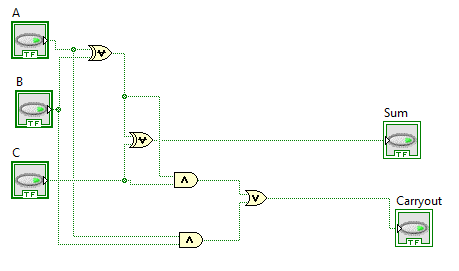
We envision this module exercise could be used as the introduction to LabView's drag and drop interface as well as a tool to help students solidify their gate level understandings. This was Emily's first hands on Labview time and one thing we liked was that all the components she had to use were in the same portion of LabView's menu. Another thing she was introduced to in this step was the use of the front panel for test cases. For those of you unfamiliar with LabView, the program provides you the visual circuit and then a front panel that allows you to change inputs and monitor outputs. For the adder exercises, we both agreed it would be useful to see how overflow errors actually happened by using the front panel and that also would help us test our error catching methods.
We then went on to create a 4 bit Adder or subtractor using the logic below. It was really easy to create subVIs that were like modules in LabView.
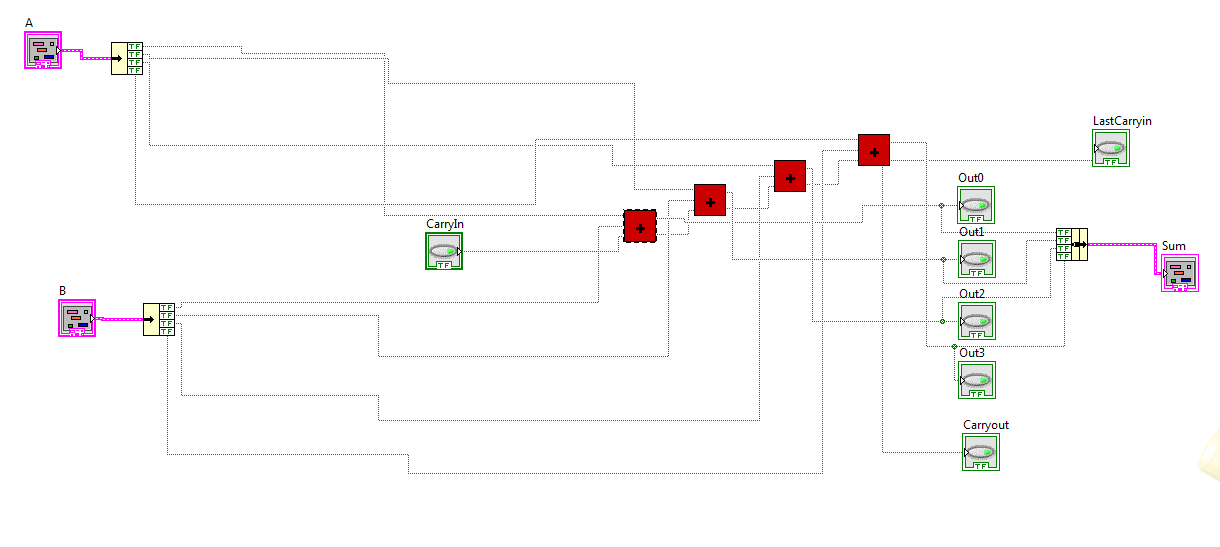 We used clusters to represent the 4 bit inputs and outputs which are comparable to nets in Verilog. This also exposed us to the port mapping that LabView uses for sub VIs. When on the front panel, you can map what components you want to be inputs and what components should be outputs. These are color coded by their types which means it's almost impossible to hook up a mismatched type to a certain operation. This is one spot where LabView outperforms Verilog because it displays readable errors and has error prevention for the issue of hooking up paths incorrectly.
We then used the adder to make an ALU. This shows the SLT we created. We used a case statement as a mux to switch between the different operations.
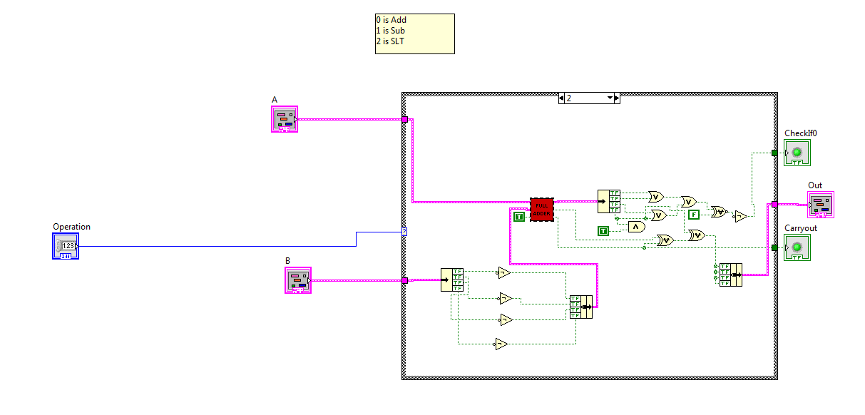
One of the best parts about LabView is that it’s easy to run and see the data flow. The image below is the front panel of our ALU. When we first tested our ALU, we realized that we weren't getting the correct outputs. We were able to use the light bulb and probe tools in LabView to easily find the error in less than 10 minutes. These tools help you to look at a subvi and identify what inputs and outputs it has as well as observe the value of a wire over the test. Similar to an oscilloscope, it can help you back track to where the data becomes invalid. It is also easy to create a test bench in LabView though we didn’t do this. You would just stick your VI inside another VI that provides all the different inputs and verifies whether the output is correct.
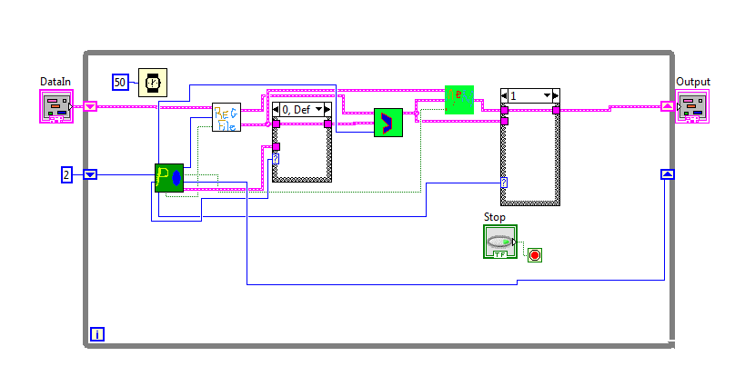
This is our instruction fetch and decode unit. The PC shift register is used to figure out what instructions to send to all the inputs in our CPU
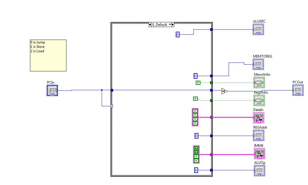 This unit introduced us to a few of the drawbacks we found. The first is that case statements as we used them to represent Mux's don't quite visually represent the process of using an address to select from many inputs. The process of constructing the mux equivalent involved hooking up each input to the output when the case state was that inputs address. This process could be avoided if people were provided with a library of muxs with different input numbers, but that too seemed a little weird.
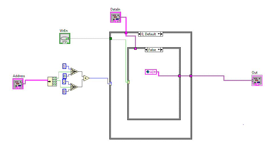 This is our memory file. We used an addition operator as well as branch statements in order to change things from binary into numbers so it would be easy to wire up our muxes. Other than this nothing from the math pallet was used in our CPU. We used global variables to represent our registers, though we later learned this was wrong. If we were going to redo this, we would use shift registers instead. Our register file was very similar to this except it only had 2 cases and outputted both registers.
How you can help The project can be extended by testing the vi's with more people of varying levels of LabView experience. Our VI's included in the zip folder, could be built upon and revised into a partially completed state for exercises. Also in the zip folder is the writeup of what components are comparable to what so that you could make a set of vi's yourself. By either using and documenting your experience with the VIs or building your own you could help further test the usability of LabView as a teaching tool. finalproject.7z
