Table of Contents
FPGA Chiptunes
What did we do?
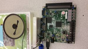
For our project, we programmed a Field Programmable Gate Array (FPGA) with Verilog that allowed a person to use the eight built-in switches as a keyboard and the four built-in buttons as a drum pad. The sounds we set out to emulate were those of the computers and game systems of the past, also known as chiptunes. An image of our setup is seen below.
Why did we do it?
We were both interested in learning about how the audio from some of our childhood games was created, and thought it tied in nicely with the things we learned throughout the course.
How did we do it?
One thing to note about our implementation of the project is that our code was written specifically for the FPGA seen in the photo, so some changes may need to be made if you have a different one that you would like to run this on.
Verilog Modules
Clock Divider
The first module that we made was a clock divider. This allowed us to slow down the built-in clock of the FPGA to audible frequencies. For reference, our FPGA's default clock frequency was 50MHz while humans can only hear up to about 20kHz. We used this website as a reference to ensure that we were upholding good practices such as not gating the clock. We instantiated eight of these modules to get square waves of eight different frequencies (we chose frequencies that made a G Major scale starting on G4). These eight square waves could then be ANDed with the eight switches on the FPGA board, and the results output through eight different General Purpose Input/Output (GPIO) pins.
Linear Feedback Shift Register
In order to make drum beat sounds, we needed to create random (or rather pseudorandom) noise. We did this by creating a Linear Feedback Shift Register (LFSR) module. An LFSR is a shift register whose serial input bit is the result of XORing a specific selection of its other bits, and it creates a pseudorandom sequence of numbers with a certain period. Here is a reference if you would like to learn more about LFSRs. The way that we used an LFSR to generate noise sounds was to shift the bits of the LFSR at a specific frequency and look at the serial output bit. Each of the four buttons was ANDed with the output of an LFSR that was shifting its bits at a different frequency, and the results were output through an additional four GPIO pins.
Circuit
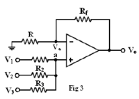
In order to use a single speaker for all twelve possible signals, we used a non-inverting summing amplifier circuit that we found here. The circuit diagram from that webpage is shown below. Our circuit differed in that we had twelve inputs rather than three. We used an LM386N-1 low voltage audio power amplifier, but just about any operational amplifier should work. Our power rails for the amplifier were +5V and 0V from a benchtop power supply. For our resistors, R = R1 = R2 = … = R12 = 1kΩ and Rf = 200Ω. Finally, we connected the output of the amplifier to one lead of an 8Ω speaker, and the other lead was connected to ground.
How can it be built upon?
All of our code is found here on GitHub. The files relevant to the keyboard/drum pad are keyBoardBringup.v, squareWave.v, noiseWave.v, and edgeDetector.v. All of the .do files were used for simulating our system using ModelSim PE Student Edition.
One of the strangest things we encountered while working on this project was finding the right amplifier power supply. We tried powering it using an Analog Discovery, regulated USB breakout, and direct USB breakout, but these all caused undesirable effects on the audio quality when more than two notes were played simultaneously. We then turned to a benchtop power supply, but had the same issue until we switched from using the variable source (set to 5V) to the dedicated 5V source. However, when we came back another day and were using a different benchtop power supply, we had the opposite problem; the dedicated 5V source caused the issues while the variable source (set to 5V) did not. We're still not entirely sure what the underlying cause of these effects was or why it was such a gamble on whether or not a power supply would give us trouble with it.
We were able to achieve our initial goals of having square wave sounds and noise sounds in a fairly timely manner. We then put quite a bit of time into improving our project, but were not able to get it working the way we wanted. There are more details on this below.
We were looking to do more with our project, namely implementing the ability to pre-program songs and have them played for you. However, we ran into some very strange issues including seemingly identical files producing different results and the FPGA ignoring the clock frequency selection jumper. It behaved as expected when simulated in ModelSim, but synthesizing and uploading to the FPGA did not produce the wonderful music we were expecting. The files relevant to our work on this are playFromFile.v, songMemory.v, increasing.dat, and all of the files from the manual version. We feel that, given another week or two, we would be able to sort out the problems we were having with this, especially since we have seen other teams have success with similar features.