This is an old revision of the document!
Table of Contents
Project Pineapple: Cats on Screens
LCD Driver on an FPGA
Steph "Grape" Northway
Dimitar "Orange" Dimitrov
Due December 16, 2014
Arduino Simulation
If you Google our screen, the ST7753 1.8“ TFT SPI display, you will quickly find Lady Ada's guide. However, short of a brief intro, it achieves little in uncovering how the display is controlled. It does link to the datasheet for the display's chip, but this 164-page document is useful for little but reference.
However, you may download Adafruit's two libraries for this chip, as well as some example code. Parsing the C++ reveals the following about screen control:
1. All signals sent are over SPI (duh). The screen returns nothing over MISO (0xFF, actually) in the default configuration.
2. There are two types of SPI signals that could be sent: “Command” and “Data”. The type is determined on the D/C input pin.
3. Command signals determine the meaning of the Data signals following (for instance, the signal 0x2C, aliased as ST7735_RAMWR, means the following data will correspond to pixel colors, which we will discuss soon)
4. At least 21 different commands (with data following) need to be sent every time the screen is powered on to configure it. Some are more simple than others, even for Ada Lovelace herself:
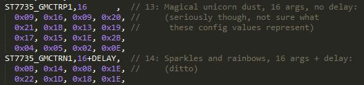 |
| Highlights from the Adafruit library code |
5. There are about 6 different combinations of these in Adafruit's library alone based on what screen you have. For ours, it was the Rcmd1, Rcmd2red and Rcmd3 sets.
6. To complicate matters further, some commands require a delay time after they're executed.
7. After initialization, there are three important commands:
- 0x2A (ST7735_CASET), which sets the start and end x-coordinates of the drawing field
- 0x2B (ST7735_RASET), which sets the start and end y-coordinates of the drawing field
- 0x2C (ST7735_RAMWR), which sets the pixel colors in the drawing field.
8. Colors are represented as two bytes according to the following diagram (from the huge datasheet):
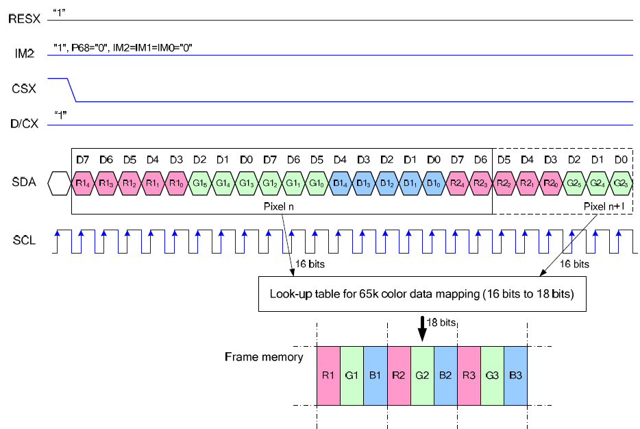 Of course, this is one of MANY options set by 0x3A (ST7735_COLMOD).
9. They are placed in consecutive order starting from the left-hand top-most pixel in the drawing area. Here's an example.
10. The screen isn't very fast. Timing needs to be slow enough, otherwise the screen does not react.
Given this information, we wrote an Arduino script using the SPI signals we would send from the FPGA.
The original code had a complicated way of keeping track of the D/C selector pin, using nested counting which would have proven difficult and wasteful to implement in Verilog. Instead, we modified the 8-bit signals, adding two bits in front of each:
- 0x0XX indicates that the signal is Data (thus the D/C pin must be HIGH when it's sent)
- 0x1XX indicates that the signal is Command (D/C LOW)
- 0x2XX indicates it is a delay
We used this encoding in both our Arduino simulation and our final Verilog. The Arduino simulation had an additional 0x300 code signifying the end of a group of signals, allowing us to iterate groups of signals and conserve space. The code for this last bit was largely inspired by code found in Adafruit's library.
Here is the full simulation code, including initialization instructions for our display, three sample color groups and sample functions iterating them. This code does not use the Adafruit library at all, and it doesn't use the Arduino SPI library (and the ATMega's hardware SPI). Instead, it manually controls SCLK, MOSI, CS, D/C and RST (used only to activate the board initially). Here's a video of these examples in action.
Unfortunately, the ATMega is too Tiny to store even a kitten. Given more space, a list of colors (which can be extracted and converted to the correct format from any jpeg using this python script) could simply be inserted as a group and written using
commandList(Kitteh)
.